Raising a House from a Drone's Point Cloud — How One Line Saying "Simpler" Ended Up Chewing Through a Wall
I used to work on building 3D maps from footage shot by drones, aircraft, and satellites. It's an application of a fairly simple technique called Structure from Motion, though it takes a fair amount of machinery — removing outliers among matched points, for one. Even so, the photos that come in are usually poor quality, and there's a limit to how many angles you can shoot from, so the resulting point clouds are never very accurate, and generating a 3D mesh from them is even harder. Most approaches settle for a rough approximation with a texture slapped on to look plausible, or lean on other data — a cadastral map, say — to trace the building's outline and add only a height value. The first approach tends to bloat the mesh and turn unnecessary detail into inaccurate noise; edges and other important shapes in particular often end up mangled. The second roughly estimates the building's height, so the height itself may come out right, but forming a roof surface that actually reflects the real building's features is quite tricky. This time, I built a real 3D shape from a series of aerial photos and had it reduced as simply as possible.
What I Asked
It started a few weeks ago with a single line.
Let's try extracting buildings from an aerial-photo point cloud as the simplest possible 3D models. Keep the roof structure, but minimize the number of faces.
In problems like this — 3D reconstruction — how you define and frame the problem is pretty much everything. I set up an appropriate objective function, laid it out, and had it work through the solution.
What Came Out
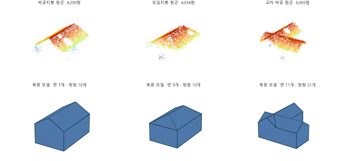
First, what a point cloud actually is. Fly a drone over a building and take a series of photos, and the same spot gets captured from slightly different angles across multiple frames. Solve for that parallax and you get 3D coordinates for each point. The result is millions of points scattered through empty space. You can see the shape, but it isn't a "building" a computer can use.
The top row is the point cloud, the bottom row the house raised from it. The gable-roofed house on the left comes out to 7 faces, 10 vertices. Saved to a file, that's 604 bytes — small, considering what went in: a handful of photos and one sentence.
You can spin it yourself in the viewer below. The same building is shown in sequence: point cloud → surface built by connecting the raw points → simplified model.
Run as-is on a point cloud built from 87 real drone photos (11.32 million points), 21 structures were identified as buildings — the 604-byte house above is one of them.
How It Worked
Why You Can't Just Connect the Points
The simplest approach is to stitch neighboring points together into triangles. Try it, and this is what you get.
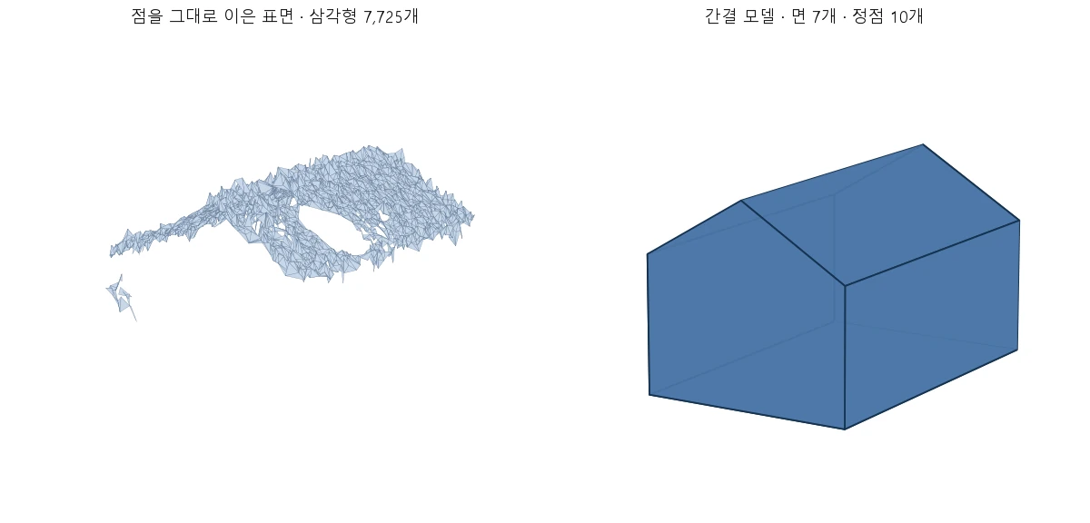
The left is the result of connecting the points directly: 7,725 triangles. The roof ripples like water, there are holes wherever points are missing, and there are no walls whatsoever — because these are photos shot looking straight down, the walls were never photographed. The right is the house built from the same point cloud: 7 faces.
The bumpiness is point error. And that error is directionally biased — since the shots were taken looking straight down, the distance error piles up almost entirely along the height axis. So no matter how carefully you connect the triangles, that error just becomes the shape.
So I Went the Other Way
Instead of connecting points, find the planes first.
- Find clusters in the point cloud where "from here to here is one flat surface." One roof surface becomes one plane.
- Align the slightly-off planes with each other — parallel or perpendicular. Skip this and one roof splits into three or four pieces.
- There's no data for walls, so they're set up as a hypothesis. Square off the outline of the roof's shadow projected onto the ground, and raise a wall perpendicular to each line.
- Use these planes like knives to slice up space. Keep cutting a box around the building with the planes, and it breaks into small rooms.
- For each room, decide "is this inside the building or outside?" A room with lots of points inside it is "in," an empty one is "out." Collect just the wall faces where inside meets outside, and that's the building's shell.
The nice thing about this approach is that conciseness comes for free. Every face that comes out lies on a "detected plane," and every edge is a line where two planes meet. Rather than generating a pile of triangles and then reducing them, it produces only as many as are needed from the start.
But the Vertices Went Their Own Way
This is where this round of improvement starts. What the method above guarantees only goes as far as the number of faces. Vertices and edges leak out on their own.
There were three reasons.
- When three planes that should meet at a single point are slightly off due to noise, the meeting point splits into two or three vertices 2–3 cm apart. The peak of a pyramidal hip roof is a typical case. A sliver of a face with almost no area gets wedged in between.
- Because faces are extracted plane by plane, where one plane's edge is cut off doesn't match where its neighbor's is. To close the topology, a vertex gets inserted in the middle of an edge — but if it's collinear on both faces, it didn't need to be there at all.
- And the thread-thin sliver faces left over from that.
All three are cases where "the shape is right, only the representation is bloated." So at the end, I had it repeat four steps until they converged.
| What it does | |
|---|---|
| Recompute | Recalculate each vertex as the intersection of the planes of the faces it belongs to |
| Merge | Combine vertices closer together than the point spacing into one |
| Prune | Remove vertices that don't bend (are collinear) on any face |
| Discard | Drop faces with near-zero area |
The first row is the crux. A polyhedron's vertex is, by definition, the point where three planes meet. Recalculate it back to that definition, and the scattered points converge to one, which makes merging easy afterward.
The threshold for "close enough to merge" wasn't a fixed number of centimeters — I made it scale with point spacing. In data where points are spaced 20 cm apart, two vertices 3 cm apart are indistinguishable to begin with, as far as the data is concerned. Keeping something indistinguishable as two separate things isn't information, it's just bulk.
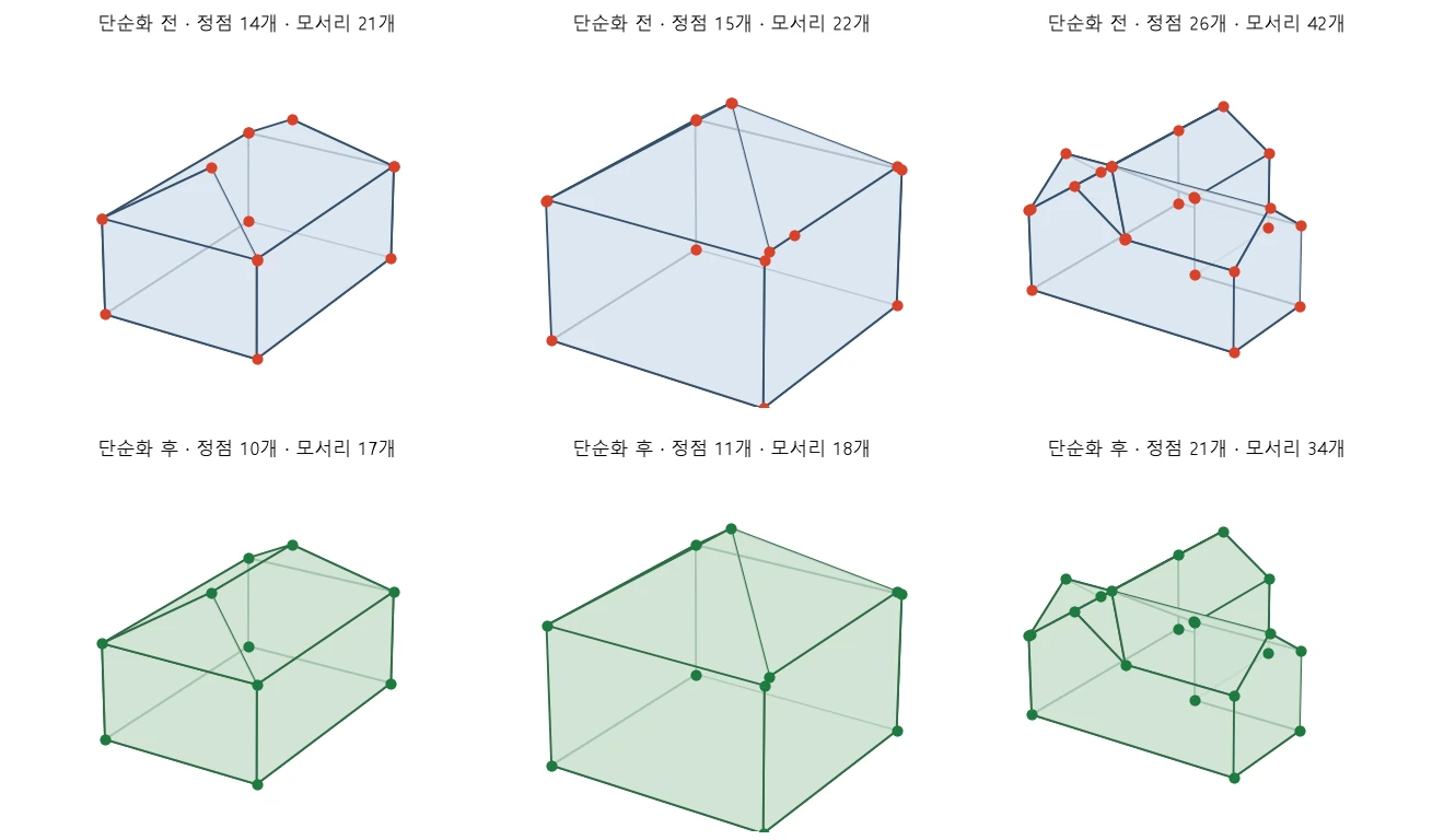
Top is before, bottom is after. The hip roof on the left goes from 14 vertices to 10. That's exactly the number in the ground-truth shape.
To be honest, these examples are just the cases that already work too well in plenty of papers.
In reality, there are far more complicated, difficult roof surfaces and distinctive landmark buildings, and simplifying those into a reconstruction is a somewhat harder problem. I built and tested several solutions, and reached a point where, whatever point cloud you feed in, it produces a simplified model that guarantees an accurate height. Since this area still has commercial potential, I won't be sharing more about it here.
So How Much Did It Shrink
I compared 160 runs each way, toggling the step on and off under identical conditions.
| Data Quality | Surface Error | Vertices | Edges | Closed Surface |
|---|---|---|---|---|
| Good | 0.152 → 0.150 m | 13.7 → 12.0 | 21.0 → 18.9 | 82% → 90% |
| Fair | 0.240 → 0.231 m | 14.8 → 13.1 | 22.5 → 20.4 | 72% → 88% |
| Poor | 0.534 → 0.531 m | 16.3 → 14.8 | 24.9 → 22.9 | 74% → 80% |
| Sparse | 0.888 → 0.879 m | 15.3 → 14.1 | 23.2 → 21.4 | 69% → 88% |
Vertices dropped 12%, edges dropped 10%, and the surface error actually got slightly lower. The error not getting worse is the whole point — it means what was cut was all representational fat, not shape.
There was one more bonus attached — the rightmost column, closed surface. That means the shell has no gaps, so "inside" is properly defined. You need this to measure volume or simulate wind and water flow. Merging vertices that had been split apart also closes the tiny gaps that used to sit at those spots, so what was 110 out of 147 became 127.
I ran the same thing on 10 real drone-derived buildings too: vertices went 463 → 417, and gaps remaining in the shell went 121 → 87.
Why One Line Was Enough
The phrase "make it simpler" isn't an instruction at all on its own. Simplicity trades off against accuracy, and without deciding how much to trade, there's no conversation to be had.
The reason one line was enough is that a grading standard already existed. In earlier work, I'd already built eight synthetic buildings with known ground-truth shapes, generated point clouds from them that mimicked photogrammetry defects (height error, missing edges, holes, clutter), and set up a mechanism to measure the distance between the reconstruction and the ground truth.
So this time, I didn't need to explain "this is a good simplification, that's a bad one." One sentence — keep the error as-is, just cut the count — was enough, and the rest was just running it 160 times and letting the numbers judge. All three of the failure modes above were caught not by my eye, but by that table.
If You Want to Try This Yourself
- Build the grading standard first. Requests like "make it better" end up as just an exchange of opinions without a scorecard. Build a scorecard using synthetic data with known ground truth, and every improvement request after that becomes one line.
- Don't measure under just one condition. This time too, there was a failure that "only shows up on clean data." Measured under just one condition, it would have sailed right through.
Most papers dealing with 3D building models tend to handle only buildings made of straight lines and flat planes, but there are, surprisingly, buildings with curved surfaces or distinctive outline structures, and it took quite a while to work out an objective function that could also handle those. In practice, beyond those simple buildings, most buildings you'd see at home or abroad can be reconstructed easily and quickly.
Actually, I'd conceived of this idea before and implemented it separately in the past; implementing the same thing in Claude Code this time took about 40 minutes. Most of that wasn't spent building the improvement — it went into verifying, repeatedly, whether the improvement actually paid off. Anyone with an understanding of mathematical models and 3D spatial models should be able to follow along just fine.